Talo: Flexible Lighting Control System
After years of building unique lights for various areas around my workshop and dorm, I decided to combine all of the controller features I use commonly into one convenient and reliable board that can be assembled by hand. This was also an experiment to test the feasibility of in-house production and assembly of complex 2-layer boards with the Protolaser LPKF laser and PCB milling system at Georgia Tech’s HIVE Makerspace.
Why?
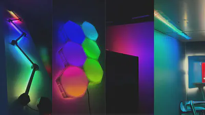
My homemade lights are fairly simple, built with 3D-printed skeletons and diffusers and filled with WS2812B addressable LEDs. To keep my entire workspace in sync, I use WLED firmware on ESP32 development boards to control the addressable strips over WiFi with Home Assistant. This allows for lighting zone automation based on occupancy and movement recorded in real-time from my DIY Pulsed Coherent Radar (PCR) sensors and camera system.
Most lights have used off the shelf chinese ESP32 breakout boards (like the WEMOS D1), but as I scaled up to use more LEDs per light, the boards started to fail from heat and firmware updates became a nightmare across different targets. To address this issue, I decided to design a custom controller PCB that would be more reliable and unify light configuration between RGB addressable and typical dimmable white lights.
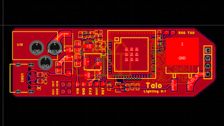
Theory & Board Design
The biggest requirements for the design of this board were:
Versatile power options
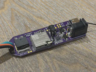
The LEDs typically draw 10-20w of power, and potentially more depending on the number of LEDs. To accomodate this in a way that doesn’t gradually kill the baord due to heat issues at any voltage between 5v and 24v, the board includes a DC barrel jack and properly set up USB-C port with circuitry to negotiate for 5V 3A mode. Both inputs feed into a TI buck converter that supplies the MCU and internal circuitry at up to 24V, while the input voltage is directly passed to the LEDs allowing for (in theory) over 100W power draw.Long Wi-Fi range
Considering the optimal position of these lights in my workspace and home, strong WiFi signal is not a given. To address this, the board uses an ESP32-S3 MCU with a W.FL connector for attaching a high-gain PCB antenna that ensures the best possible connection.Support for wide range of LEDs
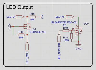
Most of the lights use WS2812B RGB and RGBW LEDs, but some use white COB leds that are driven by pure DC voltage and are not addressable. To support all of these LED solutions as best as possible, I used a FET to correctly shift the logic level from the MCU to the input voltage for addressable LEDs, and a larger FET with a separate pin broken out for driving non-addressable LEDs using an adjustable PWM duty cycle to dim.
I took a significant amount of time to choose components for this board that are easily available in the US and can be hand-assembled. The assumption from the beginning was that the board would be manufactured on OSHPARK’s Prototype 2-layer PCB line in Oregon, and the components should all be sourceable from Digikey. The main MCU is an ESP32-S3 module with onboard Pseudo-Static RAM and flash memory in an small LGA-like package. This is convenient, but also makes hand-soldering with cheaper tools impossible, requiring a hotplate or hot air rework station. All components on the board (including passives) are at least 0402 size, which is possible to hand assemble.
Assembly & Future scaling
After receiving the boards from OSHPARK, I began assembling them by hand at the Georgia Tech HIVE Makerspace using my hotplate, Chipquik paste and a stencil made on the Protolaser LPKF. All components can be reflowed in one run with no bridges if you are careful, but it will likely require some manual cleanup. All three of the boards worked as expected after being soldered, reflowed with excessive amounts of flux, and cleaned with Isopropyl alcohol.

Once everything was assembled, I designed a simple enclosure to be printed in ABS-GF (ABS Glass Fiber) on the Bambu X1C and assembled everything. This board turned out wonderfully and has been used in several lighting projects since, working flawlessly 24/7 while driving over 200 LEDs each!
More Information
If you are curious about this project, keep checking back here for updates!
The board will be open source on GitHub, and all CAD will be available after final testing and clean-up.